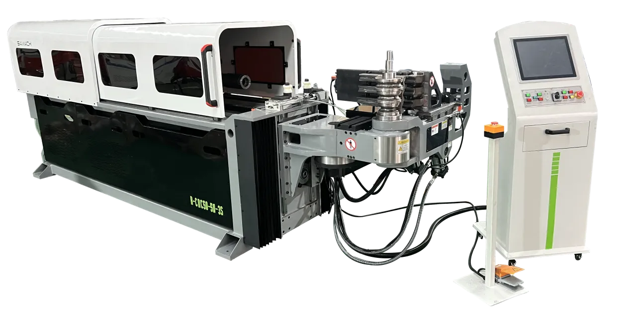
Stainless steel pipe bending may look simple, but stable results depend on more than setting an angle and running the machine. Material grade, outside diameter, wall thickness, centerline radius, tooling, and springback all affect the finished bend.
Different stainless steel grades can behave differently during forming, especially in terms of strength, work hardening, and springback. This means one set of machine parameters may not suit every pipe size or material.
This ss pipe bending machine manual explains the general setup, tooling, springback compensation, troubleshooting, safety, and maintenance principles for stainless steel pipe and tube bending. For any specific machine, the manufacturer’s own operating and safety manual should always take priority.
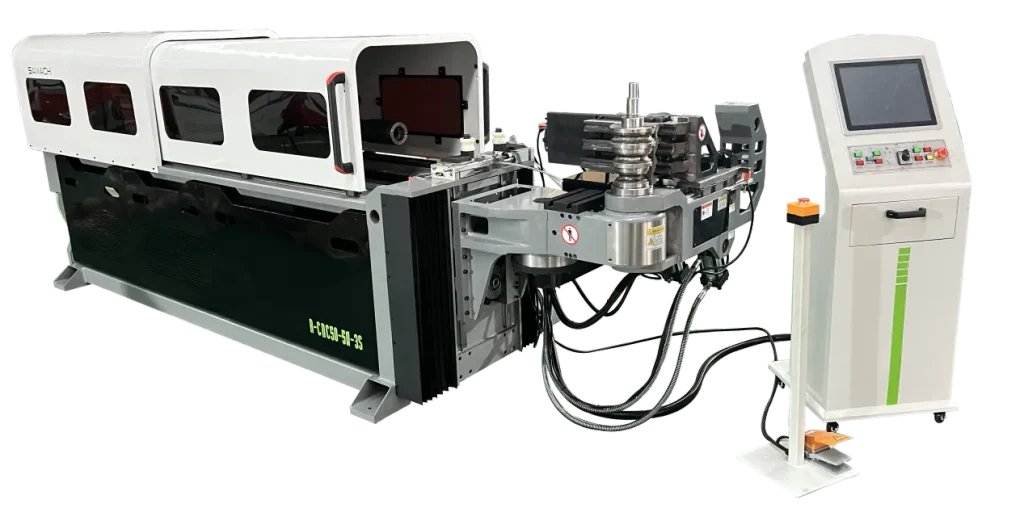
Confirm the Stainless Steel Pipe Specifications Before Setup
Good bending begins before the machine is switched on.
Simply knowing that the workpiece is “stainless steel pipe” is not enough to select tooling or establish bending parameters. The operator or process engineer should first understand the actual tube and the required finished geometry.
The most important information normally includes the stainless steel grade, outside diameter, wall thickness, required centerline radius, bend angle, and acceptable finished-part quality.
These variables influence each other.
A larger outside diameter increases the size of the tooling and generally changes the load required to form the tube. A thinner wall is more vulnerable to flattening, wrinkling, or collapse, especially as the bend radius becomes tighter. Material grade affects yield strength, work hardening, and springback.
Stainless steel itself also covers a wide range of material behaviors. Austenitic stainless steels are generally highly formable, while higher-strength grades can require greater machine capacity and tend to exhibit more springback. Published stainless-steel fabrication guidance notes that increasing strength and cold working generally increases springback, which means the same programmed angle cannot automatically be transferred from one grade to another.
Before setting up an SS pipe bending machine, it is useful to confirm:
- stainless steel grade and material condition
- actual tube outside diameter
- wall thickness
- required centerline radius
- bend angle and number of bends
- surface-finish requirements
- dimensional and ovality requirements
- production quantity
For parts with several bends in different planes, the drawing should also include the distance and rotation between bends.
One additional detail is worth confirming when ordering machinery or tooling: pipe and tube are not always dimensioned in the same way. Tube is commonly specified by actual outside diameter and wall thickness, while pipe may be described using a nominal pipe size. Providing the actual measured dimensions helps avoid tooling-selection errors.
Understand the Main Bending Tools and What They Control
In rotary draw bending, the machine does not form the stainless tube with one die alone.
Several tooling components work together, and each one controls a different part of the deformation process.
The bend die establishes the main bend geometry and centerline radius. The tube is drawn around this die during the forming cycle.
The clamp die holds the tube against the bend die so that it can rotate with the tooling instead of slipping.
The pressure die supports the straight section of tube as it enters the bend and helps control its movement during forming.
For more demanding applications, a mandrel can be inserted inside the tube. Its purpose is to support the tube wall around the bending zone and reduce excessive flattening or collapse.
A wiper die may also be used near the inside tangent of the bend. It supports material on the compression side, where excess material can otherwise begin to buckle and form wrinkles.
Whether a mandrel or wiper die is required depends on the relationship between tube diameter, wall thickness, bend radius, material, and required finished quality. Thin-wall tubes and tighter bends generally require more support than thick-wall tubes bent to generous radii.
The tooling material and surface condition also matter when processing stainless steel. Stainless steel can generate considerable friction during forming, so tooling condition, lubrication, and material compatibility should be considered when surface marking or galling becomes a concern.
The practical principle is simple: Each tooling component solves a different deformation problem.
A mandrel should not be treated as a substitute for correct clamping, and a wiper die will not correct an unsuitable bend radius or incorrect machine setup.
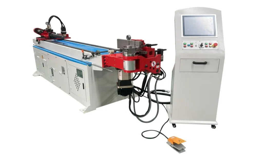
SS Pipe Bending Machine Setup: A Practical Sequence
Once the workpiece specification and tooling have been confirmed, the machine can be prepared for a trial bend.
The exact procedure differs between machine models, so the manufacturer’s own manual should be followed for installation, homing, tooling adjustment, and parameter entry. However, the overall setup logic is generally similar.
Install the Correct Bend and Clamping Tooling
Start by confirming that the bend die, clamp die, and pressure die match the tube dimensions and intended centerline radius.
Tooling should be properly seated and secured before running the machine. Contact surfaces should also be clean. Dirt, metal particles, or damaged mounting surfaces can influence alignment and may leave marks on stainless steel tubing.
Set the Mandrel When Required
If internal support is needed, install the correct mandrel for the application.
Mandrel position is important because it must support the tube in the deformation zone without creating unnecessary drag or interfering with tool release.
There is no single universal mandrel position suitable for every tube. The correct setting depends on the mandrel design, tube dimensions, bend radius, material, and machine configuration.
For this reason, fixed values copied from unrelated bending applications should not be treated as standard settings.
Position the Wiper Die When Required
When wrinkling on the inside of the bend is a concern, the wiper die should be installed and adjusted according to the tooling and machine instructions.
Its position is especially sensitive. Too little support may allow wrinkles to develop, while poor setup can create additional friction, marking, or tool wear.
Enter the Bending Parameters
Depending on the machine, operators may need to enter or adjust parameters such as bend angle, bending speed, clamping sequence, pressure-die movement, mandrel timing, feed distance, and tube rotation.
CNC equipment may also store multiple bending programs or recipes.
For example, Primapress publishes CNC pipe bending machines that support programmable bending data, manual or automatic operating modes, and material-specific springback compensation. Its product information also states that the equipment can be configured for stainless steel and other tube materials.
The initial settings should be treated as a starting point rather than proof that the finished part will already meet specification.
Run and Measure a First-Piece Bend
Before starting full production, perform a controlled trial bend.
After the tube is released from the tooling, inspect the actual result rather than relying only on the programmed machine value.
Check the final bend angle, centerline geometry, ovality, wrinkles, flattening, wall condition, and surface marks. If the part includes several bends, also confirm rotation and straight lengths between bends.
This first-piece measurement provides the information needed for accurate parameter correction.
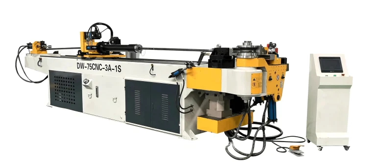
Compensating for Stainless Steel Springback
Springback is one of the most important reasons why stainless steel bending should be verified by a trial part.
During bending, part of the tube deformation is elastic. Once the bending force is released, the material recovers slightly and the finished angle changes.
The amount of springback is not fixed.
Published stainless steel forming guidance states that springback varies between grades and that changes in grade or material thickness can require machine adjustment to achieve the intended geometry. Higher-strength grades and materials with stronger work-hardening behavior generally tend to show greater springback.
This is why statements such as “stainless steel always requires X degrees of overbend” are not particularly useful.
A better procedure is empirical:
- Program the intended bend using the available machine or tooling starting values.
- Produce a first test piece.
- Release the tube completely from the tooling.
- Measure the actual finished angle.
- Compare it with the drawing requirement.
- Adjust the overbend or springback compensation.
- Bend another sample and confirm the result.
- Save the stable CNC program or production recipe.
Modern CNC bending machines can make this process easier because the compensation value can be stored with the part program.
Primapress, for example, states that springback compensation values can be entered for individual bends on its CNC pipe bending equipment, allowing the program to be adjusted for different materials and part requirements.
Even after a stable program has been established, a first-piece check remains useful when the tube supplier, grade, wall thickness, tooling, or production conditions change.
How CNC Pipe Bending Machines Handle Stainless Steel
CNC pipe bending machines are useful for stainless steel because they allow multiple forming variables to be controlled and repeated through a programmed process.
Instead of relying entirely on manual adjustment, the operator can usually enter values for bend angle, feed length, tube rotation, bending speed, clamping sequence, and springback compensation. For parts with several bends, these parameters can be stored as a program and repeated across a production batch.
This is especially helpful with stainless steel, where material strength, wall thickness, bend radius, and springback can all influence the finished geometry. Once a first-piece bend has been measured and the compensation values have been adjusted, the corrected parameters can be saved for later production.
Depending on the machine configuration, CNC systems may also coordinate several axes during the bending cycle. These can include tube feeding, tube rotation, bending movement, pressure-die motion, and mandrel retraction. Coordinating these movements can help reduce manual variation, particularly on parts with multiple bends in different planes.
However, CNC control does not eliminate the need for correct tooling or process setup. A program cannot fully compensate for an unsuitable bend radius, incorrect mandrel position, poor clamping, worn tooling, or a mismatch between the machine and the tube specification.
For this reason, CNC should be viewed as a way to improve repeatability and process control rather than as a substitute for proper tooling selection and first-piece verification.
Troubleshooting Common Stainless Steel Pipe Bending Problems
A poor bend does not automatically mean the pipe bending machine is inaccurate.
The shape of the defect often provides clues about which part of the process should be checked.
Wrinkles on the Inside of the Bend
Wrinkling develops on the compression side of the tube when material cannot remain stable as the bend forms.
If wrinkles appear, review the wiper-die setup, mandrel support, tooling position, tube wall thickness, bend radius, and pressure-die conditions.
Very tight bends in thin-wall stainless tube may require greater internal and external support than more moderate bends.
Increasing pressure without understanding the cause is not always the correct response, because excessive force may introduce other defects or increase tooling wear.
Tube Flattening or Collapse
Some ovalization is inherent in tube bending, but excessive flattening indicates that the tube cross-section is not being adequately controlled.
The mandrel is one of the main tools used to support the inside of the tube during demanding rotary draw bends.
When flattening becomes excessive, check whether a mandrel is required, whether the installed mandrel is suitable for the tube dimensions and radius, and whether it is correctly positioned.
Tooling compatibility should also be reviewed. A bend that is too tight for the selected tube and tooling combination cannot always be corrected simply by changing a machine parameter.
The Final Bend Angle Is Wrong
When the tube is consistently more open than the programmed angle after release, springback should be one of the first factors considered.
Do not assume immediately that the CNC positioning system is responsible.
Check whether the stainless grade, material condition, wall thickness, or supplier has changed. Then confirm that the correct springback compensation is being applied.
Higher-strength stainless grades can behave differently even when the nominal tube dimensions are unchanged.
Surface Scratches or Galling
Stainless steel parts are frequently used in applications where appearance and corrosion resistance are important, so surface damage may be unacceptable even when the dimensions are correct.
If scratching or galling occurs, inspect the tooling for contamination, roughness, embedded particles, worn surfaces, or transferred material.
Also review lubrication and contact conditions.
A clean tool surface is particularly important with stainless steel because contamination from other metals can affect both appearance and subsequent corrosion performance.
The solution should address the actual contact problem rather than simply polishing the finished tube after every bend.
Safety, Maintenance, and Choosing the Right SS Pipe Bending Machine
Pipe bending machines generate high clamping and forming forces, so setup and troubleshooting must always be approached with machine safety in mind.
The bend die, clamp tooling, moving tube, bending arm, and other moving components create pinch and crush zones.
Recorded industrial accidents involving tube bending equipment include severe hand injuries and amputations when operators placed their hands between bending dies and clamping jaws or attempted to reposition material while a machine was capable of cycling.
For this reason, operators should never reach into the bending area while the machine can move. Guards, interlocks, pressure mats, or other safety systems should not be bypassed.
Tool changes, cleaning, troubleshooting, and maintenance should follow the shutdown and energy-isolation procedure specified for the actual equipment. The machine manufacturer’s safety manual and applicable local workplace regulations should always take precedence over general online guidance.
Maintenance also directly affects bending quality.
Tooling should be cleaned regularly and inspected for wear, scoring, deformation, or material buildup. Mandrel components and wiper tooling should be checked when they are used in demanding bending applications. Hydraulic and mechanical systems should be maintained according to the manufacturer’s maintenance schedule.
Recurring defects should not simply be corrected by continuously increasing pressure or compensation values. If the same bend repeatedly wrinkles, collapses, scratches, or loses dimensional consistency, the tooling and application should be reviewed systematically.
Machine selection is part of this process as well.
An SS pipe bending machine should be matched to the actual workpiece range rather than selected by tube diameter alone. Material strength, wall thickness, centerline radius, number of bends, production quantity, part complexity, and automation requirements all affect the appropriate configuration.
Primapress provides CNC pipe bending equipment for materials including stainless steel and asks customers to provide detailed requirements, drawings, reference information, and application needs before a machine solution is developed.
For a stainless steel pipe bending project, useful information to provide includes the material grade, outside diameter, wall thickness, minimum required CLR, maximum bend angle, part drawing, production volume, and expected automation level.
This gives the equipment supplier a more meaningful basis for evaluating machine capacity, tooling requirements, CNC configuration, and production workflow.
Conclusion
A practical ss pipe bending machine manual is not a table of fixed settings.
Successful stainless steel tube bending begins with understanding the workpiece. Material grade, outside diameter, wall thickness, centerline radius, tooling, springback, and machine configuration all contribute to the final result.
The general workflow is straightforward:
confirm the tube specification → select the correct tooling → set the mandrel and wiper tooling when required → establish machine parameters → produce a test bend → measure springback and deformation → adjust the program → verify before production.
When defects occur, their shape should guide the troubleshooting process. Wrinkles, flattening, incorrect bend angles, and surface marks have different possible causes and should not all be corrected by simply increasing machine force.
For companies evaluating a CNC machine for stainless steel tube production, the most useful starting point is a complete part drawing and accurate material information. Primapress uses this project information to develop pipe bending equipment solutions around the customer’s actual forming requirements rather than relying on a single standard configuration.
And regardless of machine type, the specific OEM operation and safety manual remains the primary reference for installation, setup, maintenance, and safe machine use.